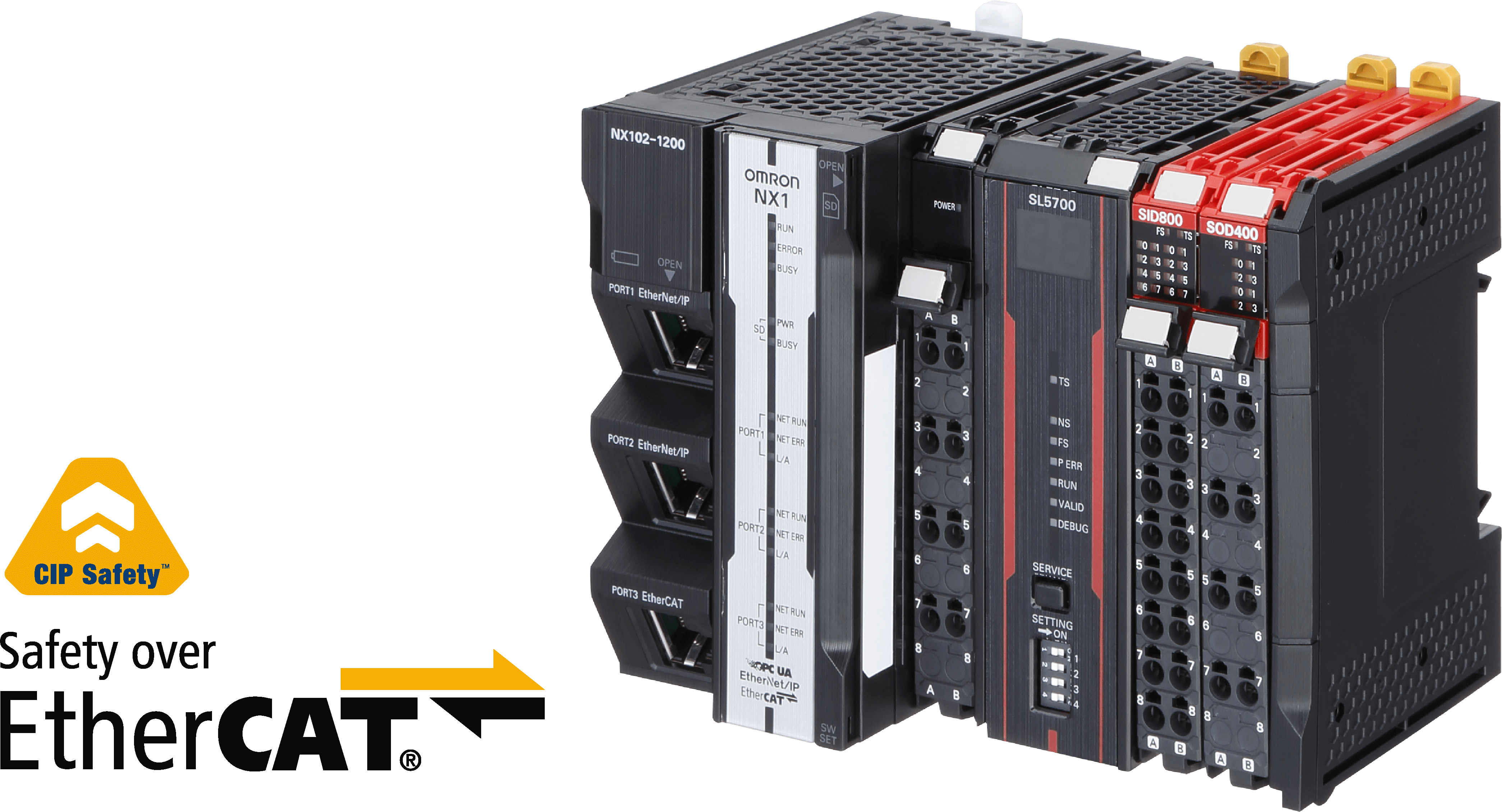
Быстрая, простая и гибкая интеграция безопасности в производственные линии, объединяющая две разные интегрированные сети: EtherNet/IP (общий промышленный протокол безопасности (CIP-S)) и EtherCAT (безопасность через EtherCAT (FSoE))
1 встроенный FSoE на главном порту EtherCAT (макс. 64 узла)
До 254 безопасных соединений с NX-SL5700
До 32 локальных модулей ввода-вывода NX
Возможна многоадресная рассылка пакетов
До 12 осей (8 синхронизированных осей движения и 4 PTP)
Подключено к модулю ЦПУ или модулю управления связью 2. Можно подключать только модули ЦПУ NX102 и модули управления связью. Модули ЦПУ NX1P2 подключить невозможно. Возможна установка в вертикальном положении.
Подключен к блоку сопряжения связи. 6 возможных ориентаций.
При подключении к модулю ЦПУ или модулю управления связью Макс. 1,05 Вт.
Подключается к блоку сопряжения связи Макс. 0,70 Вт.
При подключении к модулю ЦПУ или модулю управления связью Макс. 1,10 Вт.
При подключении к блоку сопряжения связи Макс. 0,75 Вт.
Подключено к модулю ЦПУ или модулю управления связью 2. Можно подключать только модули ЦПУ NX102 и модули управления связью. Модули ЦПУ NX1P2 подключить невозможно. Возможна установка в вертикальном положении.
Подключен к блоку сопряжения связи. 6 возможных ориентаций.
Подключено к модулю ЦПУ или модулю управления связью 2. Можно подключать только модули ЦПУ NX102 и модули управления связью. Модули ЦПУ NX1P2 подключить невозможно. Возможна установка в вертикальном положении.
Подключен к блоку сопряжения связи. 6 возможных ориентаций.
Контроллер сети безопасности Omron серии NX Контроллер безопасности CIP серии NX с возможностями EtherCAT и Ethernet/IP. Помимо нового оборудования, новые функции Sysmac Studio включают автоматическое программирование, регистрацию данных безопасности и онлайн-функциональное тестирование. Для получения дополнительной информации посетите: США Канада Мексика 03:16
Приводы 1S с функциями безопасности. Более высокая производительность и безопасная окружающая среда.
Модульные модули ввода-вывода серии NX IP20
Автономный контроллер безопасности NX-Safety Автономный контроллер безопасности NX
Информация и производительность NX1 в миниатюрном контроллере
Спецификации и заказ
CPU
Appearance
Program capacity
Variables capacity
Number of axes
Functionalities
Order code
Real axes
Motion control servo axes
Single-axis position control axes
Sequence
OPC UA
Motion
DB connection
NX102
5 MB
1.5 MB: Retained 32
MB: Not retained
12 axes
8 axes
4 axes
?
?
?
?
NX102-1220
?
?
?
-
NX102-1200
8 axes
4 axes
?
?
?
?
NX102-1120
?
?
?
-
NX102-1100
6 axes
2 axes
?
?
?
?
NX102-1020
?
?
?
-
NX102-1000
4 axes
0 axes
?
?
-
?
NX102-9020
?
?
-
-
NX102-9000
Unit type
Appearance
Specifications
Unit version
Order code
Maximum number of safety I/O points
Program capacity
Number of safety I/O connections
I/O refreshing method
Safety CPU Unit (NX-SL5 ??? )
1024 points
2048 KB
128
Free-Run refreshing
Ver. 1.3
NX-SL5500
2032 points
4096 KB
254
NX-SL5700
Unit type
Appearance
Specifications
Unit version
Order code
Number of safety input points
Number of test output points
Internal I/O common
Rated input voltage
OMRON special safety input devices
Number of safety slave connections
I/O refreshing method
Safety Input Units
4 points
2 points
Sinking inputs (PNP)
24 VDC
Cannot be connected. 2 Various OMRON special safety input devices can be connected directly without a special controller. For detail of connectable OMRON special safety input devices, refer to NX-series User's Manual Safety Control Unit/Communication Control Unit (Cat. No. Z395).
1
Free-Run refreshing
Ver. 1.1
NX-SIH400
8 points
Cannot be connected.
Ver. 1.0
NX-SID800
Unit type
Appearance
Specifications
Unit version
Order code
Number of safety output points
Internal I/O common
Maximum load current
Rated voltage
Number of safety slave connections
I/O refreshing method
Safety Output Units
2 points
Sourcing outputs (PNP)
2.0 A/point, 4.0 A/Unit at 40°C, and 2.5 A/Unit
at 55°C The maximum load current depends on the installation
orientation and ambient temperature.
24 VDC
1
Free-Run refreshing
Ver. 1.0
NX-SOH200
4 points
0.5 A/point and 2.0 A/Unit
NX-SOD400
Product name
Specifications
Number of licenses
Media
Order code
Sysmac Studio Safety Edition Ver. 1. ?? 2 The Safety Edition can be used with the Communication Control Unit and EtherNet/IP Coupler Unit.
Sysmac Studio Safety Edition is a license
including necessary setting functions for the safety control system. Note:This
product is a license only. You need the Sysmac Studio Standard Edition
DVD media to install it.
1 license
-
SYSMAC-FE001L
Sysmac Studio Standard Edition Ver. 1. ?? 2 The Sysmac Studio Standard Edition License (SYSMAC-SE2 ?? L) includes functions that the Safety Edition (SYSMAC-FE001L) provides.
The Communication Control Unit can be used with the Sysmac Studio version 1.24 or higher.
The Sysmac Studio is the software that provides
an integrated environment for setting, programming, debugging and
maintenance of machine automation controllers including the NJ/NX-series
CPU Units, NY-series Industrial PC, EtherCAT Slave, and the HMI. Sysmac
Studio runs on the following OS. Windows 7(32-bit/64-bit version)/8(32-bit/64-bit
version)/8.1(32-bit/64-bit version)/10(32-bit/64-bit version)
- (Media only)
DVD
SYSMAC-SE200D
Product name
Specifications
Order code
Memory Card
SD memory card, 2 GB
HMC-SD291
SD memory card, 4 GB
HMC-SD491
Unit/Terminal Block Coding Pins
For 10 Units (Terminal Block: 30 pins, Unit:
30 pins)
NX-AUX02
Product name
Specifications
Order code
No. of terminals
Terminal number indications
Ground terminal mark
Terminal current capacity
Terminal Block
8
A/B
Provided
10 A
NX-TBC082
8
A/B
None
10 A
NX-TBA082
16
A/B
None
10 A
NX-TBA162
Product name
Remark
Order code
End Cover
One End Cover is provided with the Communication
Control Unit.
NX-END02
Модули ЦПУ серии NX1
CPU
Appearance
Program capacity
Variables capacity
Number of axes
Functionalities
Order code
Real axes
Motion control servo axes
Single-axis position control axes
Sequence
OPC UA
Motion
DB connection
NX102
5 MB
1.5 MB: Retained 32
MB: Not retained
12 axes
8 axes
4 axes
?
?
?
?
NX102-1220
?
?
?
-
NX102-1200
8 axes
4 axes
?
?
?
?
NX102-1120
?
?
?
-
NX102-1100
6 axes
2 axes
?
?
?
?
NX102-1020
?
?
?
-
NX102-1000
4 axes
0 axes
?
?
-
?
NX102-9020
?
?
-
-
NX102-9000
Блоки управления безопасностью серии NX
Unit type
Appearance
Specifications
Unit version
Order code
Maximum number of safety I/O points
Program capacity
Number of safety I/O connections
I/O refreshing method
Safety CPU Unit (NX-SL5 ??? )
1024 points
2048 KB
128
Free-Run refreshing
Ver. 1.3
NX-SL5500
2032 points
4096 KB
254
NX-SL5700
Unit type
Appearance
Specifications
Unit version
Order code
Number of safety input points
Number of test output points
Internal I/O common
Rated input voltage
OMRON special safety input devices
Number of safety slave connections
I/O refreshing method
Safety Input Units
4 points
2 points
Sinking inputs (PNP)
24 VDC
Cannot be connected. 2 Various OMRON special safety input devices can be connected directly without a special controller. For detail of connectable OMRON special safety input devices, refer to NX-series User's Manual Safety Control Unit/Communication Control Unit (Cat. No. Z395).
1
Free-Run refreshing
Ver. 1.1
NX-SIH400
8 points
Cannot be connected.
Ver. 1.0
NX-SID800
Unit type
Appearance
Specifications
Unit version
Order code
Number of safety output points
Internal I/O common
Maximum load current
Rated voltage
Number of safety slave connections
I/O refreshing method
Safety Output Units
2 points
Sourcing outputs (PNP)
2.0 A/point, 4.0 A/Unit at 40°C, and 2.5 A/Unit
at 55°C The maximum load current depends on the installation
orientation and ambient temperature.
24 VDC
1
Free-Run refreshing
Ver. 1.0
NX-SOH200
4 points
0.5 A/point and 2.0 A/Unit
NX-SOD400
Модули ЦПУ безопасности
Unit type
Appearance
Specifications
Unit version
Order code
Maximum number of safety I/O points
Program capacity
Number of safety I/O connections
I/O refreshing method
Safety CPU Unit (NX-SL5 ??? )
1024 points
2048 KB
128
Free-Run refreshing
Ver. 1.3
NX-SL5500
2032 points
4096 KB
254
NX-SL5700
Блоки безопасного входа
Unit type
Appearance
Specifications
Unit version
Order code
Number of safety input points
Number of test output points
Internal I/O common
Rated input voltage
OMRON special safety input devices
Number of safety slave connections
I/O refreshing method
Safety Input Units
4 points
2 points
Sinking inputs (PNP)
24 VDC
Cannot be connected. 2 Various OMRON special safety input devices can be connected directly without a special controller. For detail of connectable OMRON special safety input devices, refer to NX-series User's Manual Safety Control Unit/Communication Control Unit (Cat. No. Z395).
1
Free-Run refreshing
Ver. 1.1
NX-SIH400
8 points
Cannot be connected.
Ver. 1.0
NX-SID800
Блоки безопасного вывода
Unit type
Appearance
Specifications
Unit version
Order code
Number of safety output points
Internal I/O common
Maximum load current
Rated voltage
Number of safety slave connections
I/O refreshing method
Safety Output Units
2 points
Sourcing outputs (PNP)
2.0 A/point, 4.0 A/Unit at 40°C, and 2.5 A/Unit
at 55°C The maximum load current depends on the installation
orientation and ambient temperature.
24 VDC
1
Free-Run refreshing
Ver. 1.0
NX-SOH200
4 points
0.5 A/point and 2.0 A/Unit
NX-SOD400
Стандартные модули ввода-вывода серии NX
Для выбора стандартных модулей ввода-вывода посетите веб-сайт серии NX ( https://industrial.omron.eu/en/products/nx-series).
Программное обеспечение для автоматизации Sysmac Studio
Пожалуйста, приобретите DVD и необходимое количество лицензий при первой покупке Sysmac Studio. DVD-диски и лицензии доступны индивидуально. Каждая модель лицензий не включает DVD.
Product name
Specifications
Number of licenses
Media
Order code
Sysmac Studio Safety Edition Ver. 1. ?? 2 The Safety Edition can be used with the Communication Control Unit and EtherNet/IP Coupler Unit.
Sysmac Studio Safety Edition is a license
including necessary setting functions for the safety control system. Note:This
product is a license only. You need the Sysmac Studio Standard Edition
DVD media to install it.
1 license
-
SYSMAC-FE001L
Sysmac Studio Standard Edition Ver. 1. ?? 2 The Sysmac Studio Standard Edition License (SYSMAC-SE2 ?? L) includes functions that the Safety Edition (SYSMAC-FE001L) provides.
The Communication Control Unit can be used with the Sysmac Studio version 1.24 or higher.
The Sysmac Studio is the software that provides
an integrated environment for setting, programming, debugging and
maintenance of machine automation controllers including the NJ/NX-series
CPU Units, NY-series Industrial PC, EtherCAT Slave, and the HMI. Sysmac
Studio runs on the following OS. Windows 7(32-bit/64-bit version)/8(32-bit/64-bit
version)/8.1(32-bit/64-bit version)/10(32-bit/64-bit version)
- (Media only)
DVD
SYSMAC-SE200D
Дополнительные продукты
Product name
Specifications
Order code
Memory Card
SD memory card, 2 GB
HMC-SD291
SD memory card, 4 GB
HMC-SD491
Unit/Terminal Block Coding Pins
For 10 Units (Terminal Block: 30 pins, Unit:
30 pins)
NX-AUX02
Product name
Specifications
Order code
No. of terminals
Terminal number indications
Ground terminal mark
Terminal current capacity
Terminal Block
8
A/B
Provided
10 A
NX-TBC082
8
A/B
None
10 A
NX-TBA082
16
A/B
None
10 A
NX-TBA162
Product name
Remark
Order code
End Cover
One End Cover is provided with the Communication
Control Unit.
NX-END02
Аксессуары для блока управления связью
Product name
Remark
Order code
End Cover
One End Cover is provided with the Communication
Control Unit.
NX-END02
Certification body
Standards
T?V Rheinland 2 The FSoE protocol was certified for applications in which OMRON FSoE devices are connected to each other. For compatibility with FSoE devices other than OMRON FSoE devices, the customer must validate FSoE communications.
EN ISO 13849-1EN ISO 13849-2IEC
61508 parts 1-7IEC/EN 62061IEC/EN 61131-2
UL
NRAQ (UL61010-1, and UL 61010-2-201)NRAG
(ANSI/ISA 12.12.01, or UL 121201)NRAQ7 (CSA C22.2 No. 61010-1, and
CSA C22.2 No. 61010-2-201)FSPC (IEC 61508 and ISO 13849) 2 Only
NX-SL5500/5700 have obtained IEC 61131-6 and FSPC certifications.
Item
Specifications
Enclosure
Mounted in a panel (open)
Grounding
method
Ground to 100 ? or less
Operating environment
Ambient operating temperature
Ambient operating humidity
10% to 95% (with no condensation or icing)
Atmosphere
Must be free from corrosive gases.
Ambient storage temperature
?25 to 70°C (with no condensation or icing)
Altitude
2,000 m max.
Pollution degree
2 or less: Conforms to JIS B3502 and IEC 61131-2.
Noise immunity
Conforms to IEC 61131-2. 2 kV on power supply line
Insulation class
Class III (SELV)
Overvoltage category
Category II: Conforms to JIS B3502 and IEC
61131-2.
EMC immunity level
Zone B
Vibration resistance
Conforms to IEC 60068-2-6. 5 to 8.4 Hz with 3.5-mm amplitude 8.4 to 150 Hz, acceleration of 9.8 m/s 2 100 minutes each in X, Y, and Z directions (10 sweeps of 10 min each = 100 min total)
Shock resistance
Conforms to IEC 60068-2-27. 147 m/s 2 , 3 times each in X, Y, and Z directions
Insulation resistance 2 The specifications are for the Safety Input
Unit, and Safety Output Unit, not for the Safety CPU Unit.
20 M? between isolated circuits (at 100 VDC)
Dielectric strength 2 The specifications are for the Safety Input
Unit, and Safety Output Unit, not for the Safety CPU Unit.
510 VAC for 1 min between isolated circuits,
leakage current: 5 mA max.
Installation
method
DIN Track (IEC 60715 TH35-7.5/TH35-15)
Unit name
Safety CPU Unit
Model
NX-SL5500
Maximum number of safety I/O points
1024 points
Program capacity
2048 KB
Number of safety master connections 2 This
is the maximum number of Safety I/O connections that can be set
to this Unit. The value is the total number of CIP Safety originator
connections, CIP Safety target connections, and FSoE master connections.
128
Number of CIP Safety originator connections
128
Number of CIP Safety target connections
4
Number of originators that can be connected with a multi-cast connection
8
Number of FSoE master connections
128
I/O refreshing method
Free-Run refreshing
External connection terminals
None
Indicators
Hardware switch settings
Dimensions
30 x 100 x 71 mm (W x H x D)
I/O power supply method
Not supplied.
Current capacity of I/O power supply terminals
No I/O power supply terminals
NX Unit power consumption
3.35 W max. 2 The cable length
for the Units (Communication Control Unit and Power Supply Unit
for NX Units) that supply power to the corresponding Unit must be
up to 20 m.
Current consumption from I/O power supply
No consumption
Weight
130 g max.
Installation orientation and restrictions
Installation orientation: Upright
installation Restriction 2 Only NX102 CPU Units and Communication
Control Units can be connected. NX1P2 CPU Units or Communications
Coupler Units cannot be connected. : None.
Unit name
Safety Input Unit
Model
NX-SIH400
Number of safety input
points
4 points
Number of test output
points
2 points
Internal I/O common
PNP (sinking inputs)
Rated input voltage
24 VDC (20.4 to 28.8 VDC)
OMRON special safety input devices
Can be connected.
Number of safety slave connections
1
I/O refreshing method
Free-Run refreshing
External connection terminals
Screwless clamping terminal block (8 terminals)
Indicators
Safety input current
4.5 mA TYP.
Safety input ON voltage
11 VDC min.
Safety input OFF voltage/OFF current
5 VDC max., 1 mA max.
Test output type
Sourcing outputs (PNP)
Test output load current
25 mA max.
Test output residual voltage
1.2 V max. (Between IOV and all
output terminals)
Test output leakage current
0.1 mA max.
Dimensions
12 x 100 x 71 mm (W x H x D)
Isolation method
Photocoupler isolation
Insulation resistance
20 MOhm min. between isolated circuits
(at 100 VDC)
Dielectric strength
510 VAC for 1 min between isolated
circuits, leakage current: 5 mA max.
I/O power supply method
Power supplied from the NX bus
Current capacity of I/O power supply terminals
No applicable terminals.
NX Unit power consumption
Connected to a CPU Unit or a Communication
Control Unit 1.10 W max.Connected to a Communications Coupler Unit
0.70 W max.
Current consumption from I/O power supply
20 mA max.
Weight
70 g max.
Circuit layout
Terminal connection diagram
Installation orientation and restrictions
Installation orientation: Connected to a CPU Unit or a Communication Control Unit 2 Only
NX102 CPU Units and Communication Control Units can be connected.
NX1P2 CPU Units cannot be connected. Possible in the upright
installation orientation. Connected to a Communications Coupler Unit 6 possible orientations. Restrictions:
Maximum ambient temperature is 50°C for any orientation other than
upright installation.
Protective functions
Overvoltage protection circuit
and short detection (test outputs)
Unit name
Safety Output Unit
Model
NX- SOH200
NX- SOD400
Number of safety output
points
2 points
4 points
Internal I/O common
PNP (sourcing outputs)
Maximum load current
2.0 A/point 4.0 A/Unit at 40°C 2.5 A/Unit at 55°CThe maximum load current depends on the installation orientation and ambient temperature
0.5 A/point and 2.0 A/Unit
Rated voltage
24 VDC (20.4 to 28.8 VDC)
Number of safety slave connections
1
I/O refreshing method
Free-Run refreshing
External connection terminals
Screwless clamping terminal block
(8 terminals)
Indicators
Safety output ON residual
voltage
1.2 V max. (Between IOV and all
output terminals)
Safety output OFF residual
voltage
2 V max. (Between IOG and all
output terminals)
Safety output leakage
current
0.1 mA max.
Dimensions
12 x 100 x 71 mm (W x H x D)
Isolation method
Photocoupler isolation
Insulation resistance
20 MOhm min. between isolated circuits
(at 100 VDC)
Dielectric strength
510 VAC for 1 min between isolated
circuits, leakage current: 5 mA max.
I/O power supply method
Power supplied from the NX bus
Current capacity of I/O power supply terminals
IOG: 2 A max./terminal
IOG (A3 and B3): 2 A max./terminal IOG (A7 and B7): 0.5 A max./terminal
NX Unit power consumption
Connected to a CPU Unit or a Communication
Control Unit 1.05 W max. Connected to a Communications Coupler Unit 0.70 W max.
Connected to a CPU Unit or a Communication
Control Unit 1.10 W max. Connected to a Communications Coupler Unit 0.75 W max.
Current consumption from I/O power supply
40 mA max.
60 mA max.
Weight
65 g max.
Circuit layout
Terminal connection diagram
Installation orientation and restrictions
Installation orientation: Connected to a CPU Unit or a Communication Control Unit 2 Only NX102 CPU Units and Communication Control Units can be connected. NX1P2 CPU Units cannot be connected. Possible in the upright installation orientation. Connected to a Communications Coupler Unit 6 possible orientations. Restrictions: None
Protective functions
Overvoltage protection circuit
and short detection (test outputs)
Правила и стандарты
Certification body
Standards
T?V Rheinland 2 The FSoE protocol was certified for applications in which OMRON FSoE devices are connected to each other. For compatibility with FSoE devices other than OMRON FSoE devices, the customer must validate FSoE communications.
EN ISO 13849-1EN ISO 13849-2IEC
61508 parts 1-7IEC/EN 62061IEC/EN 61131-2
UL
NRAQ (UL61010-1, and UL 61010-2-201)NRAG
(ANSI/ISA 12.12.01, or UL 121201)NRAQ7 (CSA C22.2 No. 61010-1, and
CSA C22.2 No. 61010-2-201)FSPC (IEC 61508 and ISO 13849) 2 Only
NX-SL5500/5700 have obtained IEC 61131-6 and FSPC certifications.
Блоки управления безопасностью серии NX
Блоки управления безопасностью серии NX также зарегистрированы на соответствие требованиям RCM, EAC и KC.
Certification body
Standards
T?V Rheinland 2 The FSoE protocol was certified for applications in which OMRON FSoE devices are connected to each other. For compatibility with FSoE devices other than OMRON FSoE devices, the customer must validate FSoE communications.
EN ISO 13849-1EN ISO 13849-2IEC
61508 parts 1-7IEC/EN 62061IEC/EN 61131-2
UL
NRAQ (UL61010-1, and UL 61010-2-201)NRAG
(ANSI/ISA 12.12.01, or UL 121201)NRAQ7 (CSA C22.2 No. 61010-1, and
CSA C22.2 No. 61010-2-201)FSPC (IEC 61508 and ISO 13849) 2 Only
NX-SL5500/5700 have obtained IEC 61131-6 and FSPC certifications.
Общие характеристики
Item
Specifications
Enclosure
Mounted in a panel (open)
Grounding
method
Ground to 100 ? or less
Operating environment
Ambient operating temperature
Ambient operating humidity
10% to 95% (with no condensation or icing)
Atmosphere
Must be free from corrosive gases.
Ambient storage temperature
?25 to 70°C (with no condensation or icing)
Altitude
2,000 m max.
Pollution degree
2 or less: Conforms to JIS B3502 and IEC 61131-2.
Noise immunity
Conforms to IEC 61131-2. 2 kV on power supply line
Insulation class
Class III (SELV)
Overvoltage category
Category II: Conforms to JIS B3502 and IEC
61131-2.
EMC immunity level
Zone B
Vibration resistance
Conforms to IEC 60068-2-6. 5 to 8.4 Hz with 3.5-mm amplitude 8.4 to 150 Hz, acceleration of 9.8 m/s 2 100 minutes each in X, Y, and Z directions (10 sweeps of 10 min each = 100 min total)
Shock resistance
Conforms to IEC 60068-2-27. 147 m/s 2 , 3 times each in X, Y, and Z directions
Insulation resistance 2 The specifications are for the Safety Input
Unit, and Safety Output Unit, not for the Safety CPU Unit.
20 M? between isolated circuits (at 100 VDC)
Dielectric strength 2 The specifications are for the Safety Input
Unit, and Safety Output Unit, not for the Safety CPU Unit.
510 VAC for 1 min between isolated circuits,
leakage current: 5 mA max.
Installation
method
DIN Track (IEC 60715 TH35-7.5/TH35-15)
Блоки управления безопасностью
Unit name
Safety CPU Unit
Model
NX-SL5500
Maximum number of safety I/O points
1024 points
Program capacity
2048 KB
Number of safety master connections 2 This
is the maximum number of Safety I/O connections that can be set
to this Unit. The value is the total number of CIP Safety originator
connections, CIP Safety target connections, and FSoE master connections.
128
Number of CIP Safety originator connections
128
Number of CIP Safety target connections
4
Number of originators that can be connected with a multi-cast connection
8
Number of FSoE master connections
128
I/O refreshing method
Free-Run refreshing
External connection terminals
None
Indicators
Hardware switch settings
Dimensions
30 x 100 x 71 mm (W x H x D)
I/O power supply method
Not supplied.
Current capacity of I/O power supply terminals
No I/O power supply terminals
NX Unit power consumption
3.35 W max. 2 The cable length
for the Units (Communication Control Unit and Power Supply Unit
for NX Units) that supply power to the corresponding Unit must be
up to 20 m.
Current consumption from I/O power supply
No consumption
Weight
130 g max.
Installation orientation and restrictions
Installation orientation: Upright
installation Restriction 2 Only NX102 CPU Units and Communication
Control Units can be connected. NX1P2 CPU Units or Communications
Coupler Units cannot be connected. : None.
Unit name
Safety Input Unit
Model
NX-SIH400
Number of safety input
points
4 points
Number of test output
points
2 points
Internal I/O common
PNP (sinking inputs)
Rated input voltage
24 VDC (20.4 to 28.8 VDC)
OMRON special safety input devices
Can be connected.
Number of safety slave connections
1
I/O refreshing method
Free-Run refreshing
External connection terminals
Screwless clamping terminal block (8 terminals)
Indicators
Safety input current
4.5 mA TYP.
Safety input ON voltage
11 VDC min.
Safety input OFF voltage/OFF current
5 VDC max., 1 mA max.
Test output type
Sourcing outputs (PNP)
Test output load current
25 mA max.
Test output residual voltage
1.2 V max. (Between IOV and all
output terminals)
Test output leakage current
0.1 mA max.
Dimensions
12 x 100 x 71 mm (W x H x D)
Isolation method
Photocoupler isolation
Insulation resistance
20 MOhm min. between isolated circuits
(at 100 VDC)
Dielectric strength
510 VAC for 1 min between isolated
circuits, leakage current: 5 mA max.
I/O power supply method
Power supplied from the NX bus
Current capacity of I/O power supply terminals
No applicable terminals.
NX Unit power consumption
Connected to a CPU Unit or a Communication
Control Unit 1.10 W max.Connected to a Communications Coupler Unit
0.70 W max.
Current consumption from I/O power supply
20 mA max.
Weight
70 g max.
Circuit layout
Terminal connection diagram
Installation orientation and restrictions
Installation orientation: Connected to a CPU Unit or a Communication Control Unit 2 Only
NX102 CPU Units and Communication Control Units can be connected.
NX1P2 CPU Units cannot be connected. Possible in the upright
installation orientation. Connected to a Communications Coupler Unit 6 possible orientations. Restrictions:
Maximum ambient temperature is 50°C for any orientation other than
upright installation.
Protective functions
Overvoltage protection circuit
and short detection (test outputs)
Unit name
Safety Output Unit
Model
NX- SOH200
NX- SOD400
Number of safety output
points
2 points
4 points
Internal I/O common
PNP (sourcing outputs)
Maximum load current
2.0 A/point 4.0 A/Unit at 40°C 2.5 A/Unit at 55°CThe maximum load current depends on the installation orientation and ambient temperature
0.5 A/point and 2.0 A/Unit
Rated voltage
24 VDC (20.4 to 28.8 VDC)
Number of safety slave connections
1
I/O refreshing method
Free-Run refreshing
External connection terminals
Screwless clamping terminal block
(8 terminals)
Indicators
Safety output ON residual
voltage
1.2 V max. (Between IOV and all
output terminals)
Safety output OFF residual
voltage
2 V max. (Between IOG and all
output terminals)
Safety output leakage
current
0.1 mA max.
Dimensions
12 x 100 x 71 mm (W x H x D)
Isolation method
Photocoupler isolation
Insulation resistance
20 MOhm min. between isolated circuits
(at 100 VDC)
Dielectric strength
510 VAC for 1 min between isolated
circuits, leakage current: 5 mA max.
I/O power supply method
Power supplied from the NX bus
Current capacity of I/O power supply terminals
IOG: 2 A max./terminal
IOG (A3 and B3): 2 A max./terminal IOG (A7 and B7): 0.5 A max./terminal
NX Unit power consumption
Connected to a CPU Unit or a Communication
Control Unit 1.05 W max. Connected to a Communications Coupler Unit 0.70 W max.
Connected to a CPU Unit or a Communication
Control Unit 1.10 W max. Connected to a Communications Coupler Unit 0.75 W max.
Current consumption from I/O power supply
40 mA max.
60 mA max.
Weight
65 g max.
Circuit layout
Terminal connection diagram
Installation orientation and restrictions
Installation orientation: Connected to a CPU Unit or a Communication Control Unit 2 Only NX102 CPU Units and Communication Control Units can be connected. NX1P2 CPU Units cannot be connected. Possible in the upright installation orientation. Connected to a Communications Coupler Unit 6 possible orientations. Restrictions: None
Protective functions
Overvoltage protection circuit
and short detection (test outputs)
Модули ЦПУ безопасности NX-SL5500/SL5700
Unit name
Safety CPU Unit
Model
NX-SL5500
Maximum number of safety I/O points
1024 points
Program capacity
2048 KB
Number of safety master connections 2 This
is the maximum number of Safety I/O connections that can be set
to this Unit. The value is the total number of CIP Safety originator
connections, CIP Safety target connections, and FSoE master connections.
128
Number of CIP Safety originator connections
128
Number of CIP Safety target connections
4
Number of originators that can be connected with a multi-cast connection
8
Number of FSoE master connections
128
I/O refreshing method
Free-Run refreshing
External connection terminals
None
Indicators
Hardware switch settings
Dimensions
30 x 100 x 71 mm (W x H x D)
I/O power supply method
Not supplied.
Current capacity of I/O power supply terminals
No I/O power supply terminals
NX Unit power consumption
3.35 W max. 2 The cable length
for the Units (Communication Control Unit and Power Supply Unit
for NX Units) that supply power to the corresponding Unit must be
up to 20 m.
Current consumption from I/O power supply
No consumption
Weight
130 g max.
Installation orientation and restrictions
Installation orientation: Upright
installation Restriction 2 Only NX102 CPU Units and Communication
Control Units can be connected. NX1P2 CPU Units or Communications
Coupler Units cannot be connected. : None.
Модули ввода безопасности NX-SIH400/SID800
Unit name
Safety Input Unit
Model
NX-SIH400
Number of safety input
points
4 points
Number of test output
points
2 points
Internal I/O common
PNP (sinking inputs)
Rated input voltage
24 VDC (20.4 to 28.8 VDC)
OMRON special safety input devices
Can be connected.
Number of safety slave connections
1
I/O refreshing method
Free-Run refreshing
External connection terminals
Screwless clamping terminal block (8 terminals)
Indicators
Safety input current
4.5 mA TYP.
Safety input ON voltage
11 VDC min.
Safety input OFF voltage/OFF current
5 VDC max., 1 mA max.
Test output type
Sourcing outputs (PNP)
Test output load current
25 mA max.
Test output residual voltage
1.2 V max. (Between IOV and all
output terminals)
Test output leakage current
0.1 mA max.
Dimensions
12 x 100 x 71 mm (W x H x D)
Isolation method
Photocoupler isolation
Insulation resistance
20 MOhm min. between isolated circuits
(at 100 VDC)
Dielectric strength
510 VAC for 1 min between isolated
circuits, leakage current: 5 mA max.
I/O power supply method
Power supplied from the NX bus
Current capacity of I/O power supply terminals
No applicable terminals.
NX Unit power consumption
Connected to a CPU Unit or a Communication
Control Unit 1.10 W max.Connected to a Communications Coupler Unit
0.70 W max.
Current consumption from I/O power supply
20 mA max.
Weight
70 g max.
Circuit layout
Terminal connection diagram
Installation orientation and restrictions
Installation orientation: Connected to a CPU Unit or a Communication Control Unit 2 Only
NX102 CPU Units and Communication Control Units can be connected.
NX1P2 CPU Units cannot be connected. Possible in the upright
installation orientation. Connected to a Communications Coupler Unit 6 possible orientations. Restrictions:
Maximum ambient temperature is 50°C for any orientation other than
upright installation.
Protective functions
Overvoltage protection circuit
and short detection (test outputs)
Модули вывода безопасности NX-SOH200/SOD400
Unit name
Safety Output Unit
Model
NX- SOH200
NX- SOD400
Number of safety output
points
2 points
4 points
Internal I/O common
PNP (sourcing outputs)
Maximum load current
2.0 A/point 4.0 A/Unit at 40°C 2.5 A/Unit at 55°CThe maximum load current depends on the installation orientation and ambient temperature
0.5 A/point and 2.0 A/Unit
Rated voltage
24 VDC (20.4 to 28.8 VDC)
Number of safety slave connections
1
I/O refreshing method
Free-Run refreshing
External connection terminals
Screwless clamping terminal block
(8 terminals)
Indicators
Safety output ON residual
voltage
1.2 V max. (Between IOV and all
output terminals)
Safety output OFF residual
voltage
2 V max. (Between IOG and all
output terminals)
Safety output leakage
current
0.1 mA max.
Dimensions
12 x 100 x 71 mm (W x H x D)
Isolation method
Photocoupler isolation
Insulation resistance
20 MOhm min. between isolated circuits
(at 100 VDC)
Dielectric strength
510 VAC for 1 min between isolated
circuits, leakage current: 5 mA max.
I/O power supply method
Power supplied from the NX bus
Current capacity of I/O power supply terminals
IOG: 2 A max./terminal
IOG (A3 and B3): 2 A max./terminal IOG (A7 and B7): 0.5 A max./terminal
NX Unit power consumption
Connected to a CPU Unit or a Communication
Control Unit 1.05 W max. Connected to a Communications Coupler Unit 0.70 W max.
Connected to a CPU Unit or a Communication
Control Unit 1.10 W max. Connected to a Communications Coupler Unit 0.75 W max.
Current consumption from I/O power supply
40 mA max.
60 mA max.
Weight
65 g max.
Circuit layout
Terminal connection diagram
Installation orientation and restrictions
Installation orientation: Connected to a CPU Unit or a Communication Control Unit 2 Only NX102 CPU Units and Communication Control Units can be connected. NX1P2 CPU Units cannot be connected. Possible in the upright installation orientation. Connected to a Communications Coupler Unit 6 possible orientations. Restrictions: None
Protective functions
Overvoltage protection circuit
and short detection (test outputs)